The Need
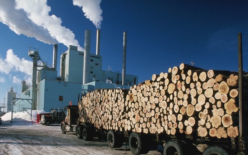
Weyerhaeuser Company’s New Bern, North Carolina facility operates a 1,000 ton per day bleached pulp mill. As part of the process, reburned lime exits a kiln, is crushed, then conveyed to a hot lime storage bin. Hot, reburned lime is then metered with fresh lime from a separate bin to a slaker to begin recausticizing.
Problems were encountered maintaining reliable feed from the hot lime bin. To solve the problems, a joint effort was made between Jenike & Johanson and a Weyerhaeuser team of technical, operating, and maintenance personnel.
The hot lime bin was designed with a small square discharge opening and a single shaft screw feeder. Hot and fresh lime were then fed into a mixing screw conveyor, which emptied into a screw conveyor to the slaker. The short discharge neck between the hot lime bin and screw feeder was subject to frequent flow interruptions. Pneumatic vibrators were rarely successful in re-establishing flow. About half of the pluggages could be cleared through the use of high pressure air hoses; however, this caused fine dust to escape from the bin/feeder flange and around the feeder cover. The standard procedure for the remaining pluggages was for the operator to employ a sledgehammer on the side of the discharge neck.
This response to pluggages was repeated many times every shift, exposing operating personnel to potential safety incidents, and creating an environmental concern due to the discharge of fine lime dust to the surrounding area. The pluggages also caused swings in slaker operation, which carried through to the causticizers, resulting in inconsistent liquor quality.
The Solution
To prevent the pluggage problems, Jenike & Johanson suggested conversion of at least a portion of the hopper to mass flow, with a larger and more robust outlet size and shape. It was not practical, nor required, to redesign the bin for complete mass flow, as flow properties tests (conducted using our unique furnace tester) showed ratholing was not a concern for larger diameter outlets. The existing cone was replaced, below the 8 ft. diameter, with a transition hopper designed for mass flow, resulting in an [modal destination=”/your-need/poor-flow/hopper-flow-pattern-expanded-flow/” link_text=”expanded flow” caption=” ” caption=”Discharge pattern combining positive features of funnel flow with mass flow”] arrangement. This enlarged the flow channel to at least an 8 ft. diameter, or about six times its previous size. It was also necessary to replace the existing feeder with a properly designed mass flow screw feeder so that the entire outlet would remain active.
A transition hopper design was selected with an outlet width large enough to overcome arching. Wall angles were selected based on wall friction test results for 304 stainless steel sheet with a 2B finish.
A dual 14 in. mass flow screw feeder was selected for use. The augers were designed with an increase in capacity in the direction of feed to accomplish the goal of withdrawing material from the entire outlet area. These features included a conical shaft section near the back of the screw to gradually reduce the shaft diameter, as well as an expansion of pitch closer to the front of the screw.
Implementation
Due to Jenike & Johanson’s experience in making such equipment and our ability to meet the required schedule, we were chosen to fabricate the dual 14 in. screw feeder, transition hopper, and a shutoff gate. We also provided detail design drawings for the modifications to be undertaken by plant personnel. Weyerhaeuser personnel executed the installation plan efficiently and without problems, resulting in a flawless startup that was on time.
It was important for the plant to have a means to shut the hopper off from the metering screw should maintenance require dropping the feeder out. Any sort of solid gate mechanism was precluded early in the design process because of clearance issues, expense, and fear that if not used over time it might not be functional when needed. We proposed a pin gate design that would induce bridging across the hopper and stop flow, which was included with the feeder as part of its supply. An opportunity to use the gate with hot lime came just a year after installation when the screw feeder had to be dropped for maintenance. The gate was successful in stopping flow.
The Result
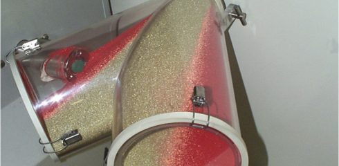
A few months after start-up, the bottom of the feeder trough, which resembles side-by-side barrels of a shotgun, began to distort and crack along its seam, due to the severe duty and heat of hot lime service. Some temporary repairs were executed and the feeder continued in operation until the next shutdown. Meanwhile, we redesigned and provided a replacement trough. After an inspection one year later, the trough still operated properly. The original screws are still in operation, without any pluggages occurring in the bin. The video camera that was required to monitor the old arrangement, to ensure that hot lime flow was maintained, was gladly retired.


