


Have you ever tried building something only to find out that it doesn’t work? You’ve followed the design plan and assembled the parts but at the end of the day it just doesn’t operate correctly. This happened to me during a recent R&D project here at J&J and I don’t want it to happen to you.
A tool that has been gaining a lot of popularity for simulating flow is Discrete Element Method (DEM) modeling. As you may have read from one of the other articles on our blog page, DEM is not a simple plug-and-play tool. It is very useful in certain applications (e.g. modeling flow through chutes) but presents many challenges in other areas of bulk solids. J&J’s expertise is in helping our clients solve or prevent flow problems and oftentimes, this means designing a mass-flow feeder interface. To better understand the limitations of DEM in this application, we initiated an R&D project to compare the DEM predictions with the flow patterns of our mass-flow interface.
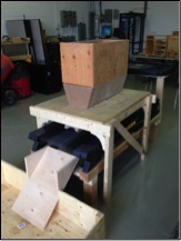
We opted to use moist -1/4” limestone as the bulk solid in our project and measured its flow properties. Then, using these properties and our traditional design methods, we fabricated a belt feeder interface. When we ran the feeder, there was significant preferential flow at the back of the interface rather than the perfect mass flow we were hoping for!!
Our DEM model and our past experience suggested that the material should discharge in mass flow. This told us something must be wrong with the physical model. So we directed our attention to the geometry and construction of the interface and noticed some inconspicuous bowing of the sidewalls. Achieving uniform discharge across the entire outlet length requires the cross-sectional area of material on the belt to expand linearly in the direction of flow.
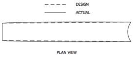
We needed to see if the subtle bowing could have affected the expansion sufficiently to cause the preferential flow. After straightening and strengthening the sidewalls the flow was much more uniform:
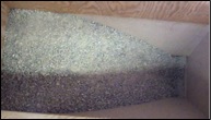

Before Strengthening Sidewalls: After Strengthening Sidewalls:
Preferential Flow Uniform Flow
The physical model was supposed to be the easy part, but it took several weeks to determine why it did not work, before we could move forward with the actual investigation. It was remarkable to be able to observe, first hand, how such a small difference could have such a dramatic consequence.
In every report we issue that gives recommendations for a mass-flow hopper or feeder interface, we provide a warning that emphasizes the importance of limiting the out-of-plane-deflection of its flat sides. I have read this message hundreds of times and have always accepted as truth. Still, when it came time to build my own interface, it did not occur to me that even at this small scale, the details would be so critical. I now BELEIVE the message and you can bet I’ll heed the warning next time. To help others benefit from my lesson-learned-the-hard-way I say: Fabrication accuracy is absolutely essential. Not only is it vital from a structural and safety standpoint, but it is also crucial from an operations and flow perspective. Your mass flow depends on it. It’s really true!